Showing posts with label antenna. Show all posts

Tuesday, January 31, 2012

Collinear Antenna Testing (indoors) Part 2, dual antenna

Round two of the indoor collinear tests. This time I used two of the 6Dbi antennas.


Below is the test data. Methodology is the same as before. Indoors tests run at 5, 10, 30 feet 1 wall, and 60 feet 2 walls. At each distance, the speed test was run 5 times. The five runs are averaged. The power settings ranged from 71mw default to 250mw maximum transmit power.

71mw

100mw

150mw

200mw

250mw

The bottleneck that arose at higher Tx powers on the single antenna were non-existant with this setup. At higher tx powers, the test device was able to approach 802.11g maximum bandwidth, which is 108mbps or 108000 kbps. It was also found that higher throughput was achieved at farther distances at higher tx powers.

Monday, January 16, 2012

Sector Antenna version 2 teardown

I decided to redesign the sector antenna backplate/reflector to make it more robust. As you can see the hot-glued antenna standouts were inadequate to deal with even transport vibrations. I have decided to use nylon  screw anchors the next time. The main differences between this and version one are as follows. Most noticeable is the copper coating on the reflector assembly. I used copper gasket spray which can be purchased at automotive parts house. The second difference is the copper insulator at the center of the antenna element. A few other people have used this method, I found it was far superior for holding everything in place and aligned. There are no other modifications done.


Testbed Part 1

I have come across a need to be able to try different antennas on the two stands I have. That led me to a removable mast system to allow for easy switching of antenna assemblies. I had some elongated thumb-screws and some threaded t-nuts. 1/4" holes in the stand and antenna assembly for the thumb-screws.


Friday, January 13, 2012

Collinear Antenna Testing (indoors)

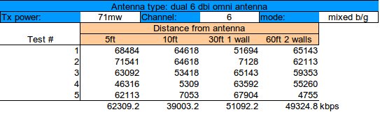
This is my first serious test. I chose to stay indoors. The antenna was located at one end of the house. I took measurements at 5, 10, 30 and 60 foot intervals. The 30 and 60 foot sections had one and two walls between the test set and the antenna respectively.
The base unit consisted of the 6dbi omni antenna, a wrt54gs v6 loaded with ddwrt build v24SP2 (build 12548M).


 The remote unit is an iPhone 3g running Ciscos GIST test app. It is the only wifi speed test app that runs without an internet connection. There seems to be some variance in the results reported by the app, either due to app/hardware integration, wifi interference, or both. Therefore I ran each distance test 5 times and averaged the speed. Below are some screenshots of the apps functionality.


Loading Screen

Main Screen

During test

Test results

To test the general usability of the antenna, I chose to test at varying transmit powers, starting with the routers default power, 71mw. Each subsequent power increase is shown in the charts below. The maximum transmit power for this particular router is 251mw. The selcted channel of operation is 6. This channel was selected by the Channel: [Auto] configuration on the wireless configuration page.

71mw

100mw

200mw

251mw

 In conclusion, within channel 6, the antenna works best in the 100mw range. Any speed over 100mw became sluggish and generally unresponsive. I am not sure if this is due to the antenna design or limits of the router. It may be that the router can only effectively radiate a given transmit power on one antenna. This has left some questions unanswered. I will build another antenna and run the test again with dual antennas. I suspect that is the solution to the slowdown at higher output.

Wednesday, January 11, 2012

Collinear WiFi Antenna

Here is a quick omni-directional antenna that requires very little time and effort to create.

Materials:
Solid copper wire, service entry wire(u.s.) works best
1" dia. schedule 40 pvc endcaps
1" dia. schedule 200 pvc pipe
n-female chassis connector
Silicone sealant

The loops are made at 60mm, 90mm, and 83mm. Each loop is 10mm in diameter.

A hole drilled in the bottom cap to accomodate the n-connector. A bit of Permatex grey gasket maker is the sealant and does a good job of holding the connector in place. 


Links:
http://martybugs.net/wireless/collinear.cgi - martybug.net's compact 6dbi collinear antenna

Tuesday, January 10, 2012

Sector Antenna version 2

After making the one sector antenna and getting a taste of the performance possibilites, I went ahead an immediately made 2 more. This time I have fewer pictures of the elements and balun area and more exterrior shots. I will say there are some issues with my initial design for the reflector backing and n-connector mounts. Therefore I will be build another two with a few design modifications I made. Here are the pics of what I have now, when I tear these units down to rebuild them, I will upload pics of the element and reflector assembly.


Sector Antenna Build version 1

The goal here was to replicate the work of others to create a low cost wifi sector antenna from off the shelf components. In many places in the United States do not have access to public wireless internet services. Maybe my interest in the subject will help others here in the States' to jump on the municipal public wifi bandwagon as the rest of the world has. Credit to Erwin Gijzen and Dragoslav Dobricic for their designs. More links to others projects below

This is my first attempt. I used material that was easily available. The total build time was 8 hours, but I'm sure it can be cut down significantly with better fabrication techniques. I will show details on my next build.

Length: 455mm, width: 62mm

The balun, 40.7mm length

The n-female connector

Standard RG-58U. This is all I had at the moment. Use LMR-400 if possible.


The Finished product is amazing. I have full wireless signal in an approximately 130 degree arc at 600 feet from the antenna, using the Cisco iphone app, CIST. I had on average 38Mbps at 300 feet and 26Mbps at 600 feet. The Antenna was mounted at 20 feet above the ground at a 10% downward tilt. Here is the test setup.  Linksys WRT-54GS v6 with dd-wrt v24 SP2 micro build firmware with hot-spot mode. I used b/g mode with auto channel selection. The transmit power was set to 125mw. (Note: The router antenna selected is the one closest to the power. This means there is a length of lmr-195 ~17cm long between the motherboard and the connector. I chose this method to test the low end of the performance envelope first.)


Links:
http://pe2er.nl/wifisector/ - Erwin Gijzen's homepage
http://www.digdice.com/12dbi-180degree-sector-wifi-antenna/ - estqwerty's digdice wireless (awesome blog)