Tuesday, January 10, 2012

Sector Antenna version 2

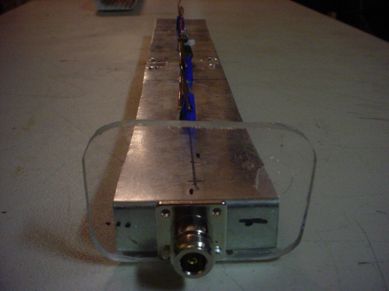
After making the one sector antenna and getting a taste of the performance possibilites, I went ahead an immediately made 2 more. This time I have fewer pictures of the elements and balun area and more exterrior shots. I will say there are some issues with my initial design for the reflector backing and n-connector mounts. Therefore I will be build another two with a few design modifications I made. Here are the pics of what I have now, when I tear these units down to rebuild them, I will upload pics of the element and reflector assembly.


Radio Hardware Overview

Here is a selection of the hardware I am using for the radio portions. The units I chose to use in the test role were upgraded with headsinks and fans. The fan is from a Pentium III slot 1 processor from a very old server. A bit of weather stripping to seal it off and a 3-pin fan connector with a 100ohm resistor soldered to the motherboard supply. With the modifications, I can run each of the routers at full Tx power, 251mw, without any reliability issues. Mild overclocks are tolerated at full Tx power, but I haven't had a chance to do any real overclocking.

Linksys WRT54G version 2, dd-wrt version v24 sp2 mega build.


Linksys WRT54GS version 6, dd-wrt v24 sp2 micro build, with hotspot.


Linksys WRT54GS version 2, dd-wrt v24 sp2

Sector Antenna Build version 1

The goal here was to replicate the work of others to create a low cost wifi sector antenna from off the shelf components. In many places in the United States do not have access to public wireless internet services. Maybe my interest in the subject will help others here in the States' to jump on the municipal public wifi bandwagon as the rest of the world has. Credit to Erwin Gijzen and Dragoslav Dobricic for their designs. More links to others projects below

This is my first attempt. I used material that was easily available. The total build time was 8 hours, but I'm sure it can be cut down significantly with better fabrication techniques. I will show details on my next build.

Length: 455mm, width: 62mm

The balun, 40.7mm length

The n-female connector

Standard RG-58U. This is all I had at the moment. Use LMR-400 if possible.


The Finished product is amazing. I have full wireless signal in an approximately 130 degree arc at 600 feet from the antenna, using the Cisco iphone app, CIST. I had on average 38Mbps at 300 feet and 26Mbps at 600 feet. The Antenna was mounted at 20 feet above the ground at a 10% downward tilt. Here is the test setup.  Linksys WRT-54GS v6 with dd-wrt v24 SP2 micro build firmware with hot-spot mode. I used b/g mode with auto channel selection. The transmit power was set to 125mw. (Note: The router antenna selected is the one closest to the power. This means there is a length of lmr-195 ~17cm long between the motherboard and the connector. I chose this method to test the low end of the performance envelope first.)


Links:
http://pe2er.nl/wifisector/ - Erwin Gijzen's homepage
http://www.digdice.com/12dbi-180degree-sector-wifi-antenna/ - estqwerty's digdice wireless (awesome blog)

Tuesday, January 3, 2012

Solar Charged DC powerbox

I needed a method to get power to my test rigs. Since the Linksys routers run on 12v, I figured this would be the best bet. I had some old 12v 5.2 amp hour batteries from an old ups. They had cracked at the bottom, so I purchased a replacement at my local Fry's electronics. I chose a 12v 7.2 amp hour, sealed lead-acid. I purchased a Sunforce60032 30 amp Digital Charge controller, and 2 1.8 watt Sunforce solar cells. I chose the larger, more expensive controller so I could use it for a house mounted system I am designing. You can get by with the 7 amp model.


I found a plastic container that was real tupperware from the late 50s that used to be my grandmas. A little paint, and a few holes for the wires and venting. There is an inline fuse holder with a 3 amp fuse for the load. The wiring is a bit shoddy, but this is a prototype. The main switch I harvested from a leaf blower that had died a week before.


The external connection is a molex plug. The two other connectors are for the Sunforce photo-voltaic cells.


And here we can see voltage on each of the two switch settings. Low and High respectively.


Here shown plugged into the WAP.


I have used this for over a week. I can have 3 or so hours at medium 125mw radio output. It takes 6 or so hours full sun to charge it fully.

Cantenna style antenna

My first foray into building wifi antennas started with a satellite dish and a biquad antenna I fabricated. It worked fairly well at long distances. Very difficult to aim. Blow is my proposed design for my second long range setup. My design criteria are as follows:
  • Durable Design; take wind, water, and vibration
  • Ease of fabrication; time, money factors
  • Ease of duplication
  • Availability of materials
I have done research into 3rd world wifi setups and I have come across some ideas that may help people trying to set these things up in their countries.

This is the first design as per criteria.


I have seen 20 dBi of gain from properly designed cantennas. You can check my links below for design credit.

Materials:
_______________________________________________________________________________

4"x2ft steel dryer tube
1/4" rivets
metal coffee can lid
aluminum tape
n-female chassis connector
n-male to rp-tnc male pigtail

Antenna Body
______________________________________________________________________________

I utilized dryer vent material purchased from local builder superstore. I dont have welding skills, so to create the cylinder, pop rivets were utilized.
Dimensions:
Diameter: 3.25"
Length: 9.5 "
Element hole: 2.75" from back

 
To close off the bottom, a coffee can lid trimmed to the proper dimensions was taped with aluminum tape.


I originally used screws with nylon bolts to affix the n-connector to the tube, but they were difficult to tighten properly. I used a healthy amount of permatex white gasket material instead.

Antenna Element:
_________________________________________________________________________________

Solder a piece of romex (service entry electrical wire) cut to 30 mm or 1.21" long into the n-connector. The total exposed length should be 30mm or 1.21"


The finished antennas were sprayed with automotive primer on the outside. They were affixed with pipe clamps to a 2x4" piece of pressure treated wood.

WAP
_________________________________________________________________________________

Linksys WRT54G v2.0 Flashed with DD-WRT v
Modified with heatsinks for increased Tx power and overclocking if necessary


I wanted to create a weatherproof setup without having to purchase a weatherproof enclosure. To sum it up, dont. Way to much hassle with the foam. One could maybe use expanding foam and forms...but hey buy a weatherproof WAP if you can get one in your area. Otherwise pics below.

OXO brand plastic food container with rubberized seal. Painted grey for asthetics.


As you can see i cut stiff foam pieces and covered them with tape to keep the balls from coming off. A bit of hotglue to adhere them to the box. Next I fabricated a motherboard backing from a piece of high-impact abs plastic I had lying around. I drilled 1.8" holes in it after marking the motherboard screw holes. I then threaded motherboard standouts into the holes.


The next step was to mock up the motherboard and the weatherproofing foam in the weatherproof box.


With the motherboard and weatherproofing fitted correctly, I drilled holes at the top and bottom of the enclosure to allow for cabling. I used 1" piping and a t fitting at the top to accommodate larger LMR-400 cable at a later time. Grommets will be installed at that time. For now, I created small foam plugs to go into the ends to resist weather entering the enclosure.


The final Product:


Conclusion:
With a bit of internet research and basic tools, a setup like this can be made in a few hours time. This particular antenna would be used in a point-to-point deployment. I will post testing results next.

Links:
Tin Can Waveguide Antenna: http://www.turnpoint.net/wireless/cantennahowto.html (has calculator for can length and element length)
Pringles Cantenna : http://www.seattlewireless.net/PringlesCantenna